PICで省エネ時計を作る
概要
PICで時計
久しぶりにPICの話題です。しばらくESP8266やARMマイコンなど、上級のマイコンを使っていましたが、またPICを使ってみたくなりました。
他のマイコンには真似できないような超低消費電力の時計を作ってみました。
PIC18F27J53の機能
今回用いるPICマイコンは、以前このブログでも紹介したPIC18F27J53 です。
リアルタイムクロック内蔵
32.768kHzの水晶発振子をつなぐだけで時計をカウントしてくれるのがリアルタイムクロックモジュールです。
時計なんてソフトウェアでカウントしても数行のコードで作ることができますが、リアルタイムクロックモジュールはスリープ中やリセット中でも動作を続けるという魅力的な特徴があります。
そんなリアルタイムクロックがハードウェアで内蔵されているのです。
ディープスリープ機能
PIC18F27J53には、超低消費電力のディープスリープモードがあります。
PICの電源を完全に切って、消費電力を極限まで抑えます。しかし、リアルタイムクロックは動作を続けます。
できたもの
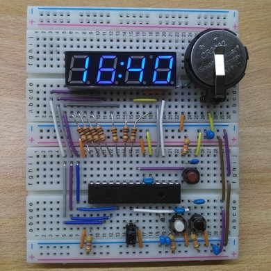
写真
今回は、とりあえずブレッドボードで作りました。
ブレッドボードでの製作ですが、見た目の美しさにこだわりました。
PICで時計

表示をオンオフ
写真の中の赤いタクトスイッチを押すと表示/非表示を切り替えることができます。
非表示中は、ディープスリープモードになっており、電力をほとんど消費しません。
時計の精度
この時計の精度は、水晶発振子に依存するので、いい水晶発振子を使えば、精度は高くなります。
さらに、ソフトウェアで微調整をすることができます。
実際に電力を測ってみる
Analog Discovery でどのくらい電流を消費しているのかを調べてみます。
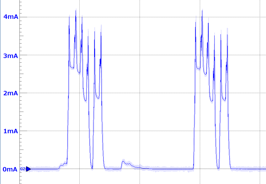
7セグLEDのダイナミック点灯の様子
7セグLED表示中が2.5mA程で、スリープ中はほぼ0mAです。
ダイナミック点灯

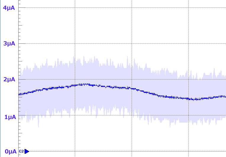
ディープスリープの様子
平均1.5uA程であることがわかります。
deep sleep

バッテリーの持ち時間の概算
CR2032(容量:220mAh3.0V)を用いて考えます。
常にLEDを表示した場合
平均電流は、1mAなので、約220時間つまり、9日程度。
この場合、ディープスリープを使えないので、あまり持たないですね…
表示をオフにした場合
平均電流は、1.5uAなので、約146,000時間=6,100日間、つまり16年ほど持つ計算になります。すごいですね!!!
ソフトウェア
最新のプログラムはこちら にあります。
main.c
/*
 * Title:   PIC18F27J53 Low Power Clock
 * Date:	2016.09.12
 * Author:	kerikun11
 */

// CONFIG1L
#pragma config WDTEN = OFF      // Watchdog Timer (Disabled - Controlled by SWDTEN bit)
#pragma config PLLDIV = 2       // PLL Prescaler Selection (Divide by 2 (8 MHz oscillator input))
#pragma config CFGPLLEN = OFF   // PLL Enable Configuration Bit (PLL Disabled)
#pragma config STVREN = OFF     // Stack Overflow/Underflow Reset (Disabled)
#pragma config XINST = OFF      // Extended Instruction Set (Disabled)
// CONFIG1H
#pragma config CPUDIV = OSC1    // CPU System Clock Postscaler (No CPU system clock divide)
#pragma config CP0 = OFF        // Code Protect (Program memory is not code-protected)
// CONFIG2L
#pragma config OSC = INTOSC     // Oscillator (INTOSC)
#pragma config SOSCSEL = HIGH   // T1OSC/SOSC Power Selection Bits (High Power T1OSC/SOSC circuit selected)
#pragma config CLKOEC = OFF     // EC Clock Out Enable Bit  (CLKO output disabled on the RA6 pin)
#pragma config FCMEN = OFF      // Fail-Safe Clock Monitor (Disabled)
#pragma config IESO = OFF       // Internal External Oscillator Switch Over Mode (Disabled)
// CONFIG2H
#pragma config WDTPS = 1024     // Watchdog Postscaler (1:1024)
// CONFIG3L
#pragma config DSWDTOSC = T1OSCREF// DSWDT Clock Select (DSWDT uses T1OSC/T1CKI)
#pragma config RTCOSC = T1OSCREF// RTCC Clock Select (RTCC uses T1OSC/T1CKI)
#pragma config DSBOREN = OFF    // Deep Sleep BOR (Disabled)
#pragma config DSWDTEN = OFF    // Deep Sleep Watchdog Timer (Disabled)
#pragma config DSWDTPS = G2     // Deep Sleep Watchdog Postscaler (1:2,147,483,648 (25.7 days))
// CONFIG3H
#pragma config IOL1WAY = OFF    // IOLOCK One-Way Set Enable bit (The IOLOCK bit (PPSCON<0>) can be set and cleared as needed)
#pragma config ADCSEL = BIT12   // ADC 10 or 12 Bit Select (12 - Bit ADC Enabled)
#pragma config MSSP7B_EN = MSK7 // MSSP address masking (7 Bit address masking mode)
// CONFIG4L
#pragma config WPFP = PAGE_127  // Write/Erase Protect Page Start/End Location (Write Protect Program Flash Page 127)
#pragma config WPCFG = OFF      // Write/Erase Protect Configuration Region  (Configuration Words page not erase/write-protected)
// CONFIG4H
#pragma config WPDIS = OFF      // Write Protect Disable bit (WPFP<6:0>/WPEND region ignored)
#pragma config WPEND = PAGE_WPFP// Write/Erase Protect Region Select bit (valid when WPDIS = 0) (Pages WPFP<6:0> through Configuration Words erase/write protected)
#pragma config LS48MHZ = SYS48X8// Low Speed USB mode with 48 MHz system clock bit (System clock at 48 MHz USB CLKEN divide-by is set to 8)

#include <xc.h>
#include <stdint.h>
#include "7seg.h"

#define _XTAL_FREQ 4000000

void dinamic(void) {
    static uint8_t dinamic_counter = 1;
    static uint8_t sec, min, hou, wkd;
    switch (dinamic_counter) {
        case 1:
            print_7seg(4, '0' + (min & 0x0F));
            TMR1L += 0xF0;
            break;
        case 2:
            print_7seg(3, '0' + (min >> 4));
            TMR1L += 0xF0;
            break;
        case 3:
            print_7seg(2, '0' + (hou & 0x0F));
            TMR1L += 0xF0;
            break;
        case 4:
            if (hou & 0xF0) print_7seg(1, '0' + (hou >> 4));
            else print_7seg(1, ' ');
            TMR1L += 0xF0;
            break;
        case 5:
            print_7seg(5, RTCCFGbits.HALFSEC ? ' ' : ':');
            TMR1L += 0xF0;
            break;
        default:
            print_7seg(-1, ' ');
            RTCCFGbits.RTCPTR0 = 1;
            RTCCFGbits.RTCPTR1 = 0;
            while (RTCCFGbits.RTCSYNC);
            hou = RTCVALL;
            wkd = RTCVALH;
            sec = RTCVALL;
            min = RTCVALH;
            dinamic_counter = 0;
            break;
    }
    dinamic_counter++;
}

void interrupt ISR(void) {
    if (INTCONbits.INT0IE && INTCONbits.INT0IF) {
        INTCONbits.INT0IF = 0;
        INTCONbits.GIE = 0;
        print_7seg(-1, ':');
        DSCONHbits.DSEN = 1;
        SLEEP();
    }
    if (INTCON3bits.INT1IE && INTCON3bits.INT1IF) {
        INTCON3bits.INT1IF = 0;
        if (PORTAbits.RA5 == 0) {
            print_7seg(-1, ' ');
            RTCCFGbits.RTCPTR0 = 0;
            RTCCFGbits.RTCPTR1 = 0;
            while (RTCCFGbits.RTCSYNC);
            uint8_t val = RTCVALH;
            val = ((val >> 4)*10 + (val & 0x0F) + 1) % 60;
            RTCCFGbits.RTCPTR0 = 0;
            RTCCFGbits.RTCPTR1 = 0;
            RTCVALH = ((val / 10) << 4) + ((val % 10)&0x0F);
            RTCVALL = 0;
        }
    }
    if (INTCON3bits.INT2IE && INTCON3bits.INT2IF) {
        INTCON3bits.INT2IF = 0;
        if (PORTCbits.RC2 == 0) {
            print_7seg(-1, ' ');
            RTCCFGbits.RTCPTR0 = 1;
            RTCCFGbits.RTCPTR1 = 0;
            while (RTCCFGbits.RTCSYNC);
            uint8_t val = RTCVALL;
            val = ((val >> 4)*10 + (val & 0x0F) + 1) % 24;
            RTCCFGbits.RTCPTR0 = 1;
            RTCCFGbits.RTCPTR1 = 0;
            RTCVALL = ((val / 10) << 4) + ((val % 10)&0x0F);
        }
    }
    if (PIE1bits.TMR1IE && PIR1bits.TMR1IF) {
        PIR1bits.TMR1IF = 0;
        TMR1H = 0xFF;
        dinamic();
    }
}

int main(void) {
    OSCCONbits.SCS = 0;
    DSCONLbits.RELEASE = 0;
    TRISA = 0b01110001; // RA7, RA6, RA5, Vcap, RA3, RA2, RA1,  RA0
    TRISB = 0b00000001; // RB7, RB6, SDA, SCL,  RB3, RB2, RB1,  RB0
    TRISC = 0b00111110; // RXD, TXD, D+,  D-,   Vusb,RC2, T1OSI,T1OSO
    ANCON0 = 0b11111111; // x,x,x,AN4(RA5),AN3(RA3),AN2(RA2),AN1(RA1),AN0(RA0)
    ANCON1 = 0b00011111; // VBG,x,x,AN12(RB0),AN11(RC2),AN10(RB1),AN9(RB3),AN8(RB2)

    // Timer1
    T1CON = 0b10001101;
    PIE1bits.TMR1IE = 1;

    // RTC
    EECON2 = 0x55;
    EECON2 = 0xAA;
    RTCCFGbits.RTCWREN = 1;
    RTCCFG = 0b10100000;
    RTCCAL = 0x00;

    // INT0
    INTCON2bits.INTEDG0 = 0;
    INTCONbits.INT0IF = 0;
    INTCONbits.INT0IE = 1;

    // INT1
    RPINR1 = 2; // INT1 -> RP2
    INTCON2bits.INTEDG1 = 0;
    INTCON3bits.INT1IF = 0;
    INTCON3bits.INT1IE = 1;

    // INT2
    RPINR2 = 13; // INT2 -> RP13
    INTCON2bits.INTEDG2 = 0;
    INTCON3bits.INT2IF = 0;
    INTCON3bits.INT2IE = 1;

    // Enable Interrupts
    INTCONbits.PEIE = 1;
    INTCONbits.GIE = 1;

    while (1) {
        SLEEP();
        NOP();
    }
    return 0;
}
7seg.h
/*
 * File:   7seg.h
 * Author: kerikun11
 *
 * Created on 2016/09/10, 9:00
 */

#ifndef _7SEG_H
#define	_7SEG_H

#ifdef	__cplusplus
extern "C" {
#endif

#include <xc.h>
#include <stdint.h>

    void print_7seg(uint8_t col, char c);

#ifdef	__cplusplus
}
#endif

#endif	/* 7SEG_H */
7seg.c
#include "7seg.h"

#define SEG_1   LATA1
#define SEG_2   LATA2
#define SEG_3   LATC7
#define SEG_4   LATC6
#define SEG_5   LATA3

static void print_column(uint8_t col) {
    SEG_1 = (col == 1);
    SEG_2 = (col == 2);
    SEG_3 = (col == 3);
    SEG_4 = (col == 4);
    SEG_5 = (col == 5);
}

static void print_pattern(uint8_t pat) {
    LATB = ~pat;
}

void print_7seg(uint8_t col, char c) {
    // BGACDEHF
    static uint8_t pattern[10] = {
        0b10111110, //0
        0b10010000, //1
        0b11101100, //2
        0b11111000, //3
        0b11010010, //4
        0b01111010, //5
        0b01111110, //6
        0b10110010, //7
        0b11111110, //8
        0b11111010, //9
    };
    uint8_t pat;
    switch (c) {
        case ' ':
            pat = 0b00000000;
            break;
        case ':':
            pat = 0b10100000;
            break;
        case '-':
            pat = 0b01000000;
            break;
        case '0':
        case '1':
        case '2':
        case '3':
        case '4':
        case '5':
        case '6':
        case '7':
        case '8':
        case '9':
            pat = pattern[c - '0'];
            break;
        default:
            pat = 0b00000010;
            break;
    }
    print_column(0);
    print_pattern(pat);
    print_column(col);
}
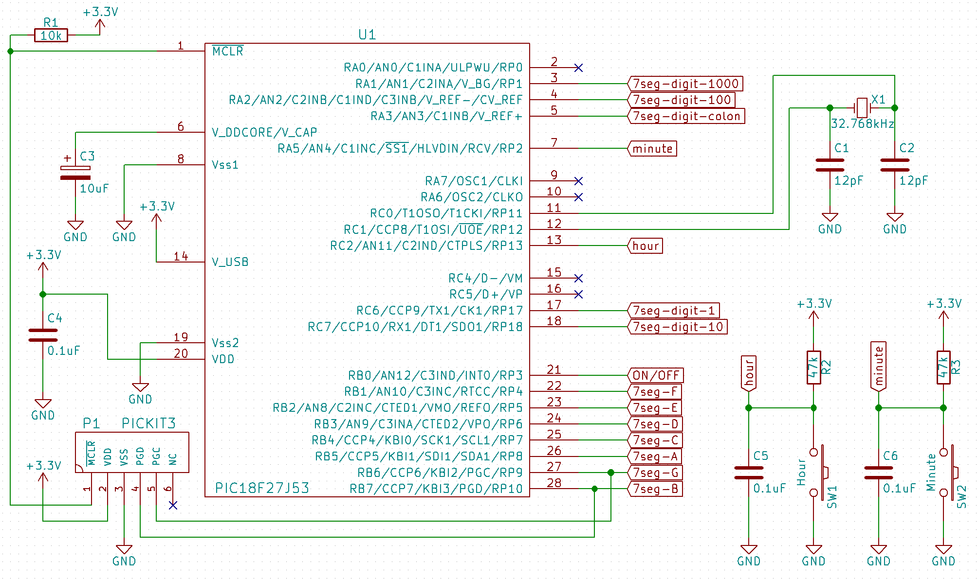
回路図
7セグLEDはこちら を使いました。
回路図

まとめ
久々にPICを触りましたが、素直でいいやつですね~
PICのいいところは、内部の構造をかなり理解して使えるとことろ。ブラックボックスなんていやだ!
さてさて、次は何を作りましょうかね。PICは魅力的なマイコンです。